How I Fixed My SonarQube Server After a Failed Update

Last week I updated my SonarQube server running on Ubuntu 20.04.4 LTS and ended up in a situation in which all code scans of a certain project ran into a database-related error. In this blog post I’d like to summarize the update process, the error and how I fixed it.

First Things First: Make a Backup

Seriously, make a backup of your database before you update your SonarQube server. It saved me in this case. Backups should be made regularly, but it does not hurt to do another backup to ensure the latest state is saved after shutting down your server.

Determining the Migration Path

Read the upgrade guide to find out which intermediate LTS versions are required to upgrade to your desired version. In my case the migration path was:

7.9.1 -> 7.9.6 LTS -> 8.9.7 LTS

A list of all LTS versions can be found on the downloads page.

Downloading and Extracting New Versions

Downloading and extracting the new versions is pretty straight-forward. In my case each version is stored in separate subfolders, so that I can go back to another version if needed. Of course you can choose other paths on your system, but /opt/sonarqube seems to be a decent location on Ubuntu (or Linux in general). Make sure that you still have a copy of the old version, especially the config files.

1
2
3
4
5
cd /opt/sonarqube
sudo wget https://binaries.sonarsource.com/Distribution/sonarqube/sonarqube-7.9.6.zip
sudo unzip sonarqube-7.9.6.zip
sudo rm sonarqube-7.9.6.zip
sudo chown -R sonarqube: /opt/sonarqube/sonarqube-7.9.6/

Configuring the New Version

The next step is to transfer your configuration settings into the installation of the new version. To that end, compare the conf/sonar.properties files from the old and the new installation. Copy uncommented lines from the old to the new configuration file. The most important ones are:

  • sonar.jdbc.username
  • sonar.jdbc.password
  • sonar.jdbc.url

Reconfiguring the Service

In case you are using a systemd service to start and stop your server (which is recommended), the service script located at /etc/systemd/system/sonarqube.service must be updated to the new version. In my case the script looks like this:

1
2
3
4
5
6
7
8
9
10
11
12
13
14
15
16
17
18
19
[Unit]
Description=SonarQube Service
After=syslog.target network.target
 
[Service]
Type=forking
 
ExecStart=/opt/sonarqube/sonarqube-7.9.6/bin/linux-x86-64/sonar.sh start
ExecStop=/opt/sonarqube/sonarqube-7.9.6/bin/linux-x86-64/sonar.sh stop
 
LimitNOFILE=131072
LimitNPROC=8192
 
User=sonarqube
Group=sonarqube
Restart=always
 
[Install]
WantedBy=multi-user.target

In order to reload the changes, execute

1
sudo systemctl daemon-reload

Wait a few seconds until the changes are reloaded, then start SonarQube:

1
2
sudo systemctl start sonarqube.service
sudo systemctl status sonarqube.service

The final step is to visit the web interface of your server at ${sonar.url}/setup to perform the database migration.

Before analyzing code, it is recommended to perform a cleanup of obsolete tuples in the database:

1
2
3
4
psql -U postgres -h localhost
\c sonarqube
vacuum full;
\q

The Database Inconsistency

Everything worked for me so far, but when I started analyzing code all analysis processes failed with an error like the following:

org.postgresql.util.PSQLException: ERROR: there is no unique or exclusion constraint matching the ON CONFLICT specification
SQL: insert into live_measures ( uuid, component_uuid, project_uuid, metric_id, value, text_value, variation, measure_data, created_at, updated_at ) values (...)
on conflict(component_uuid, metric_id) do update set
  value = excluded.value,
  variation = excluded.variation,
  text_value = excluded.text_value,
  measure_data = excluded.measure_data,
  updated_at = excluded.updated_at
where
  live_measures.value is distinct from excluded.value
  or live_measures.variation is distinct from excluded.variation
  or live_measures.text_value is distinct from excluded.text_value
  or live_measures.measure_data is distinct from excluded.measure_data

At first I did not understand what was wrong because there were no apparent errors during the update. So I decided to start over, revert to the old version and to re-import my database backup. It took me some time to figure out the right parameters for the PostgreSQL command line to restore a SQL dump; I posted a separate blog post on this topic.

Unfortunately, the database backup could not be restored because of an error relating to a unique constraint on the columns component_uuid and metric_id in relation live_measures. My table data contained duplicate tuples for combinations of component_uuid and metric_id.

Fortunately I found this thread explaining how to find and eliminate the duplicates. After eliminating the duplicates I could add the constraint again:

1
CREATE UNIQUE INDEX live_measures_component ON public.live_measures USING btree (component_uuid, metric_uuid);

After fixing the inconsistency, I repeated the update process and code scans were now mostly successful. However, Gradle builds failed with the following error:

Execution failed for task ':sonarqube'.
> Unable to load component class org.sonar.scanner.report.ActiveRulesPublisher

I could solve this by deleting the directories data/es6 and temp in the active SonarQube installation. So in case something went wrong, it is a good idea to delete those folders in order to rebuild the elastic search indices.

Now my intermediate version was running without issues and I repeated the whole update process for the next and final LTS version.

I hope this post will help you to update your SonarQube servers as well.

Basic PostgreSQL Commands on Linux

In this post I collected some useful commands for PostgreSQL administration on Linux.

PostgreSQL Interpreter

In order to start an interpreter accepting SQL statements and other PostgreSQL commands, execute:

1
psql -U postgres -h localhost

The database user is specified with -U postgres and -h stands for host name. In this case we assume the database runs on the same machine.

The password must be entered before proceeding. It is also possible to store the password in an environment variable as follows (use with caution and make sure not to expose the variable permanently):

1
export PGPASSWORD="My Password"

You should see a command prompt like this:

psql (13.2 (Ubuntu 13.2-1.pgdg18.04+1), Server 10.16 (Ubuntu 10.16-1.pgdg18.04+1))

postgres=#

The prompt accepts any SQL statements, terminated with semicolons. For example, to list tables in the database, enter:

1
SELECT schemaname, tablename FROM pg_tables;

To change the database, type:

\c database_name

A command to list all tables in the current database is:

\dt

To remove obsolete tuples and optimize the database, execute:

vacuum full;

To quit, enter:

\q

Creating Backups

To create SQL dumps of your databases, use the following command from the Linux shell:

1
pg_dump -U user -h localhost -c --if-exists database_name > backup.sql

The flags -c and --if-exists are optional and will generate drop table if exists commands in the SQL dump.

Restoring Backups

Backups can be restored with the following command:

1
psql -U user -h localhost -d database_name -f backup.sql

Synchronizing Files with Seafile Using the Linux Command Line Client

Today I managed to get a seafile client running on a Linux server and decided to write the necessary steps down in the hope that this will be helpful.

Installing the Command Line Client

Instructions on how to install seafile-cli: can be found here. For Ubuntu 20.04, the commands are:

1
2
3
4
sudo wget https://linux-clients.seafile.com/seafile.asc -O /usr/share/keyrings/seafile-keyring.asc
sudo bash -c "echo 'deb [arch=amd64 signed-by=/usr/share/keyrings/seafile-keyring.asc] https://linux-clients.seafile.com/seafile-deb/focal/ stable main' > /etc/apt/sources.list.d/seafile.list"
sudo apt update
sudo apt install seafile-cli

Initializing the Configuration Directory

Seafile needs a directory in which configuration data is stored. It is created and initialized as follows:

1
2
3
mkdir ~/seafile-client
seaf-cli init -d ~/seafile-client
seaf-cli start

Synchronizing the Files

The hardest part is to construct the command line for the sync command. It should look like this:

seaf-cli sync -l '1b71943d-392a-d9f2-c336-a2d681956ace' -s 'https://myserver.org' -d '/path/to/local/directory' -u 'user@domain.org' [-p 'MyPassword' -e 'MyLibraryPassword']

Possible pitfalls:

  • The library ID must be provided (as opposed to the library name). To find out the library ID, browse the contents on the Seafile web interface. The ID is part of the URL.
  • Although the documentation states that a user name is required, it is actually the user’s email address that has to be provided. When providing user names, the program fails with the error Bad request
  • If your password contains special characters (and it should!) then it has to be enclosed in single quotes (double quotes do not work)

Note: if passwords are not provided on the command line, the program asks for them during program execution, that’s why they are marked as optional.

That should be it hopefully 😉 Now you can check what the client does in the background with

1
seaf-cli status

How to Clone a HD/SSD to a Larger HD/SSD on Linux Systems

For an Ubuntu 20.04 server, I bought a new SSD and wanted to replace the existing SSD. Of course I wanted to keep all the existing data and replicate it to the new drive. In my case, the old SSD had a cpacity of 250 GB and the new one 500 GB. I decided to summarize how I achieved this for future reference and hope that it might be useful to someone else as well.

Make Backups

Before doing anything, make backups of everything because the following operations are not trivial and might damage the file system.

Connect the New Drive

Shut down the server and connect the new HD/SSD to your mainboard. Once connected, the new drive should show up when entering the command lsblk on the console.

Create a Clonezilla Live USB Stick

To clone the SSDs, I used the excellent tool Clonezilla. The instructions how to create a bootable USB stick can be found here. Once the stick is ready, plug it into your server and reboot. While rebooting, press the key for your mainboard’s boot menu (this is mainboard-specific, in my case it was F11) and choose the USB stick. Alternatively, reconfigure the sequence of the boot devices in your BIOS. The key to get into the BIOS configuration on startup is also mainboard-specific, but in most cases it is the DEL (delete) key.

Clone the Existing Drive to the New Drive

Once clonezilla is started, follow these instructions.

My clonezilla initially wouldn’t start up because it hung at the step Configuring keyboard. I could solve this by editing the command line for the clonezilla option. For that, highlight the option Clonezilla live (to RAM) and then press e. Now you should be able to edit the command line. Locate the parameter keyboard-layouts= and set a value, for example in my case keyboard-layouts=de (an American keyboard layout would be keyboard-layouts=us). Then press Ctrl + X to start Clonezilla.

For reference, I chose the following options:

  • Ask which action to take after finishing the clone operation
  • No file system checks

I am aware that this could also be achieved using dd, but this is not the best solution because this will result in a lot of unnecessary write operations on the new drive. Background: dd copies every single byte, even from areas on the source drive that don’t contain any data (zero bytes). Refer to this askubuntu page for more details.

After clonezilla finished, disconnect the new drive and then reboot the machine with only the new drive connected. If everything worked fine, your server should start up exactly as before.

Adjust the Partition Size

Run the command lsblk again. You will notice that the new drive still shows the capacity like the old drive. The reason is that the partition tables were also copied, and these now still contain the values for the old drive.

To update the partition table, run the command parted with the partition to be altered as parameter. For example, if the new drive has the device name /dev/sdc and the second partition is the one to be altered, run parted /dev/sdc2. In parted, enter print to show the partitions again and verify the number of the partition to be altered (in my case 2).

In the next step, enter resizepart 2 (if 2 is the partition number). You will be promted for the new size of the partition. Because I wanted the partition to take all the remaining space, I entered the complete size of the new SSD (in my case 500GB). Because of the boot partition, which takes about 512 MB and some additional space needed for the file system, the effective size of the partition is smaller (about 465 GB), but higher values can be entered, resulting in the remaining available space automatically.

The last step is to make the whole partition size available to the filesystem. This is done with the command resize2fs /dev/sdc2 (adjust device and partition name accordingly), which works for ext2, ext3 and ext4 file systems. I found the essential information about this part on this stackexchange page.

That’s all. I hope this will help you to upgrade your Linux system drives.

Connecting Emoncms with openHAB

In this post I’ll explain how energy data from Emoncms can be made visible in openHAB. My scenario is as follows: I have Emoncms running on a dedicated Raspberry Pi and openHAB running on another server. This will also work if you have both systems running on the same machine. My goal was to make the energy data visualized in Emoncms available in openHAB and display it there, too.

Find the MQTT Configuration

First, we need to find the MQTT configuration for EmonHub. This can be found on the Emoncms web interface by navigating to Setup | EmonHub | Edit Config | Section [[MQTT]]

We will need this data later to connect the MQTT broker.

Install the MQTT Binding in openHAB

On your openHAB web interface, open the Paper UI and install the MQTT binding:

Add an MQTT Broker

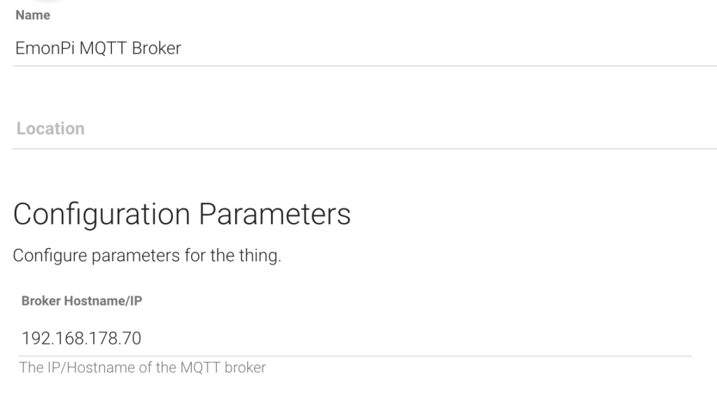
In the openHAB Paper UI, add a new thing of type MQTT Broker. As broker hostname/IP, enter localhost or 127.0.0.1 if your Emoncms installation is on the same device. Otherwise, enter the local IP address of the machine running Emoncms.

Also, the username and password you configured in the MQTT configuration of your EmonHub (see above) must be entered:

Add a MQTT Thing

Now we can create a thing representing your Emoncms / EmonPi. Select the broker you just created as bridge.

Create channels for each value you want to transfer between Emoncms and openHAB. For example, for my first power value I created a new Number Value Channel and entered the following MQTT State Topic:

emon/node1/power1

The exact name depends on your Emoncms configuration. In the example, a node named node1 is configured which receives power values in a channel named power1.

We now have a number value channel in openHAB which looks like this:

Add openHAB Items

For each channel we can now create items an openHAB items file. For the channel above, my item looks like this:

Number:Power Energy_Power1 "Power 1 [%d W]" <energy> (gEnergy) { channel="mqtt:topic:fc2fe9b1:power1" }

Note that I have defined a group named gEnergy in my openHAB configuration. You can read more about group configurations here. Now we can use the item Energy_Power1 in openHAB (for example in sitemaps). Create other channels and items accordingly. Now you can monitor your energy data in Emoncms and openHAB at the same time 🙂

How I Fixed a Boot Loop during a LineageOS Upgrade

Today I upgraded my Android smartphone from LineageOS 16.0 to 17.1 and I decided to share some insights since I ran into several issues.

Upgrading the Recovery Image

According to the LineageOS upgrade documenation, “a newer LineageOS version may not install due to an outdated recovery”. When upgrading from 16.0 to 17.1, a new recovery image is mandatory. This is how you install it (you need to have adb and fastboot installed for that):

  • Download the recovery image for your smartphone
  • Reboot your phone into bootloader mode using the command adb reboot bootloader (the LED should now flash blue)
  • Check if the phone is properly connected using fastboot devices
  • Upload the new recovery image with fastboot flash recovery <your recovery filename>.img

The output should be similar to this:

Sending 'recovery' (13528 KB) OKAY [ 0.496s]
Writing 'recovery' OKAY [ 0.917s]
Finished. Total time: 1.426s

Note that the new recovery has no touch display input anymore. Instead, you can navigate using the the volume up and volume down keys. The power button is used as enter key.

Upgrading LineageOS and Google Apps

First, you need to download the new LineageOS image for your phone. In case you have Google Apps installed, you also need a new Google Apps package your the processor architecture of your phone (in my case this was arm and I chose the nano package).

The required steps are:

  • If not already enabled, activate USB debugging in your phone’s settings (Settings | System | Developer Options | Root Debugging or in older versions Root Access Options / ADB only)
  • Start sideloading in recovery using adb reboot sideload
  • Sideload the LineageOS image with adb sideload <your LineageOS image>.zip Note: on the phone a confirmation message will be shown that the process was successful, but on the computer the following confusing error message will appear: adb: failed to read command: Undefined error: 0. You can simple ignore this error as long the phone reports success.
  • Directly after sideloading the OS image, sideload the Google Apps (without rebooting in between!): Apply Update | Apply from ADB, then on your computer type adb sideload <google apps filename>.zip. Here I got the error signature verification failed once. I chose Install anyway on the phone to continue.
  • Navigate to the back arrow at the top left of the screen using the volume up key and confirm with the power button, then choose Reboot system now.

If you’re lucky, you’re already done now. If you encounter issues, continue reading.

Possible Issues

I encountered the following issues:

  • I tried installing 17.1 with the 16.0 recovery image. It does not work, you need to flash the 17.1 recovery first.
  • After sideloading my computer displayed the error adb: failed to read command: Undefined error: 0, while the phone displayed a success message. This is very confusing, but the error in the terminal can be ignored as long as the phone displays a success message.
  • My phone got stuck in a boot loop. With the old recovery image, there was no way to solve it. With the new recovery image, after a few minutes a screen appeared saying that “the Andorid system could not be started” with the options Try again and Factory Reset. At this point do not immediately perform the factory reset, in my case I was able to repair the installation. Apparently, a faulty Google Apps package caused the problems. The problematic package was open_gapps-arm-10.0-nano-20200919.zip. When I looked at the download page again, a package from the day before was provided: open_gapps-arm-10.0-nano-20200918.zip. With the “older” package it suddenly worked. Before, I had also tried different LineageOS image versions.

Bottom line: if you are in a boot loop situation, first try different versions of LineageOS images and also different Google Apps images. Remember to always install the LineageOS package first and then the Google Apps package directly afterwards. In some cases the boot loop can be solved like this.

The combination that ultimately worked for me was:

  • lineage-17.1-20200915-recovery
  • lineage-17.1-20200915-nightly
  • open_gapps-arm-10.0-nano-20200918

Now I can enjoy Android 10 Features on a 6 year old smartphone 😎

List of Useful Linux Commands

This post contains a collection of useful Linux commands for the Ubuntu distribution. The list is extended every time I find a new handy command. Most of the commands are also applicable to other Linux distributions. Use commands in red with caution.

File System Commands

Description Example
Display Current Working Directory pwd
Change Current Working Directory cd /path/to/directory
Show All Files in Current Directory (Including Hidden Ones) ls -la
Show Sizes of All Files and Directories in Current Directory du -sh *
Show Available Disk Space df -h
Copy File cp /source/file /destination/file
Move or Rename File mv /source/file /destination/file
Create Directory mkdir myDirectory
Delete File rm /path/to/file
Delete Directory Recursively rm -rf /path/to/directory
Create Symbolic Link ln -s /path/to/target /path/to/symlink
Change File Permissions (non-recursive) sudo chmod 644 /path/to/file
Change File Permissions (recursive) sudo chmod -R 644 /path/to/directory
Change Owner of File (non-recursive) sudo chown user:group /my/path
Change Owner of Symbolic Link (non-recursive) sudo chown -h user:group /my/symlink
Change Owner of Files / Directories (recursive) sudo chown -R user:group /my/path
Count Files (recursive) find /my/path -type f | wc -l
List Number of Files (recursive) for Each Subfolder find . -type f | cut -d/ -f2 | sort | uniq -c
Find Files Older Than a Specified Number of Days (non-recursive) find /path/to/directory -maxdepth 1 -mtime +60 -type f -print
Find Files Older Than a Specified Number of Days (recursive) find /path/to/directory -mtime +60 -type f -print
Delete Files Older Than a Specified Number of Days (non-recursive) find /path/to/directory -maxdepth 1 -mtime +60 -type f -delete
Delete Files Older Than a Specified Number of Days (recursive) find /path/to/directory -mtime +60 -type f -delete
Show All Disks and Partitions lsblk
Show File Systems for all Disks and Partitions lsblk -f
Format Partition with File System sudo mkfs -t ext4 /dev/sdf2
Mount Drive sudo mount /dev/sdd2 /mnt/mountpoint/
Mount USB Stick pmount /dev/sdf1
Unmount USB Stick pumount /dev/sdf1
File System Commands

Viewing, Editing and Comparing Files

Description Example
Display File Contents cat /path/to/file
Edit File sudo nano /path/to/file
View End of File less +G /path/to/file
View End of File and Update Automatically tail -f /path/to/file
Compare Files in Two Directories Recursively diff -rq /path/to/dir1 /path/to/dir2
Viewing, Editing and Comparing Files

User Management

Description Example
List All Users cut -d: -f1 /etc/passwd
List All Groups cut -d: -f1 /etc/group
Add New User sudo adduser john
Show Groups a User is Assigned to groups john
Add User to Group usermod -a -G examplegroup john
User Management

Package Management Commands

Description Example
Update Package Index sudo apt update
List Upgradable Packages apt list --upgradable
Upgrade Installed Packages sudo apt upgrade
Install Security Updates sudo unattended-upgrade -v
List All Installed Packages apt list --installed
Show Version of Installed Package apt list <package name>
Package Management Commands

Network / Internet / Firewall Commands

Description Example
Check Host Availability ping [IP or hostname]
Download File curl -O [URL]
List Open Ports sudo lsof -i -P -n | grep LISTEN
Open Firewall to Specific Port from Local Subnet sudo ufw allow from 192.168.1.0/24 to any port 22
Delete Firewall Rule by Number sudo ufw status numbered
sudo ufw delete 42
Connect to FTP Server ftp myserver.org
Connect to SFTP Server sftp user@myserver.org
Network and Firewall Commands

Controlling 433 MHz Power Outlets with openHAB

I’m currently building a home automation system based on the incredibly powerful openHAB 2 platform. We already have a few remotely switchable 433 MHz power outlets by the manufacturer Brennenstuhl in our home which we currently switch using the provided remote controls. I was wondering whether we could control them from the OpenHAB platform as well, and indeed found a way to achieve this.

My openHAB 2 instance does not run on a Rasberry Pi, but on a dedicated Ubuntu Server. If your platform is Raspberry, your hardware setup and configuration might be different, but still I think this article will be useful for the OpenHAB binding configuration.

Hardware

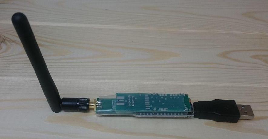
First, I looked for a suitable device capable of sending and receiving 433 MHz signals. I ended up with a nanoCUL device connected via USB. There are many DIY nanoCUL kits available on the internet that you can assemble yourself, but there are also pre-built nanoCULs available. I chose the latter and ordered an assembeled nanoCUL USB device including an antenna and a USB adapter. It looks like this:

nanoCUL with antenna and USB adapter

OpenHAB Binding

After some research I found a suitable binding to integrate nanoCUL with openHAB: it is called Intertechno Binding. It is an older v1 binding, and is not displayed in my Bindings list after the installation (even when activating the Include Legacy 1.x Bindings option). But it works nonetheless.

To configure the nanoCUL, edit the file services/culintertechno.cfg and add the following configuration:

1
2
3
device=serial:/dev/ttyUSB1 
baudrate=38400
parity=NONE

You have to adjust the device (in my case /dev/ttyUSB1) to the device matching the nanoCUL on your system. To find out which device it is, I used a script I found in this stackexchange answer.

Binding the Device using a Unique Identifier

After a few reboots I discovered an issue: sometimes, the nanoCUL was bound to /dev/ttyUSB1, other times to /dev/ttyUSB0. This lead to errors and conflicts in openHAB. To solve this problem, I used a device path like the following in services/culintertechno.cfg:

1
device=serial:/dev/serial/by-id/<id of your nanoCUL>
You can find the device ID of your nanoCUL using
1
ls -la /dev/serial/by-id/
But when I started openHAB2, the following error occurred:
1
org.openhab.io.transport.cul.CULDeviceException: gnu.io.NoSuchPortException
I found out that this can be solved by adding the device path to the java startup options of openhab2. In my case, these can be configured in /etc/default/openhab2:
1
EXTRA_JAVA_OPTS="-Dgnu.io.rxtx.SerialPorts=/dev/serial/by-id/<id of your nanoCUL>"
After adding the option and restarting openhab2 with sudo service openhab2 restart, the error disappeared and now the system has the correct device association after every reboot.

Item Configuration

The tricky part was to find out which codes to send to switch the power outlets on or off. After long research, I found this FHEM Wiki page which finally helped me to figure out the codes. The power outlets are configured with DIP switches like the following:

The first 5 switches identify the logical group of power outlets. The remote control that comes with the power outlets has the DIP switches 1-5 only (excluding A-E). A-E identifies one of 5 power outlets in the group.

To derive the code to be sent from openHAB, you just have to translate the switch states into a sequence of 0 and F, where 0 corresponds to “switch up” and F corresponds to “switch down” (I did not get why “switch up” is encoded with a lower value than “switch up”, but anyway this is how it works for me). So for the switch states shown above, the code is

0F00FF0FFF

This is the basic code to address a specific power outlet in a specific group, where the first five digits encode the group and the last five hex digits the outlet in the group. To control whether the outlet should be turned on or off, one the following two codes has to be appended: FF = ON or F0 = OFF. So in conclusion, to switch on the above outlet, the complete code is

0F00FF0FFFFF

and to switch it off, the code is

0F00FF0FFFF0

In the item configuration, this is added as follows:

1
Switch MyOutlet_B "My Outlet B" {culintertechno="type=raw;commandOn=0F00FF0FFFFF;commandOff=0F00FF0FFFF0"}

And that’s it folks, it works like a charm for me 🙂 I hope this post will be useful to others who want to integrate their 433 MHz power outlets in openHAB.

Update for OpenHAB 3

The Intertechno Binding is not supported anymore on openHAB 3, but I found a way to control 433 MHz devices using the Serial Binding. After some research I found out that the intertechno binding basically just sends the command string (described in detail in the previous section) prefixed with the string is and followed by a newline character to a serial interface. So for the example above, the resulting string looks like this:

is0F00FF0FFFFF\n

To send commands via the serial binding, first create a serial bridge with the following settings:

  • Serial Port: the USB port where the nanoCUL is connected, e.g. /dev/ttyUSB0 or /dev/serial/by-id/<id of your nanoCUL>
  • Baud Rate: 38400
  • Data Bits: 8
  • Parity: None
  • Stop Bits: 1

Create a new serial device for each outlet to be connected. Choose the serial bridge created in the previous step as parent bridge. For the pattern match setting (which is required) I entered a regular expression matching everything: .*

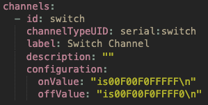
The next step is to add a switch channel with the following settings:The tricky part is to add a newline character to the command. If it is added to the command string in the UI directly, \n is interpreted as the literal sequence of a backslash and the character n, not as newline. The trick is to switch to the Code tab, add double quotes around the commands and then insert \n:

After saving the configuration, the commands are sent correctly. If you want to change the command later, the UI presentation is a bit strange: there are pipe sysmbols, the quotes and the newlines are gone and the commands are in the next lines, respectively:

If you want to modify the command again, you have to restore the state as shown in the first screenshot. Not sure if this the intended UI behavior. But anyways it it possible to add newlines as illustrated in the first screenshot.

A post that helped me a lot in which I also shared my solution can be found here.

Generating EMF Models from XML Schema Definitions (XSDs)

In this blog post I will show how to generate models for the Eclipse Modeling Framework (EMF) out of an XML schema definition. EMF is a powerful framework which allows you to create Java classes corresponding to the XML schema types, code to load XML documents to Java models and code to serialize Java models back to XML again. As an example, I will use MusicXML schema definitions.

Installing Required Features

To work with EMF and XSD schemas, you need to install the following features in your Eclipse development environment:

  • EMF – Eclipse Modeling Framework SDK
  • XSD – XML Schema Definition SDK

You can check for already installed in the About dialog of your Eclipse installation. In case the features are not installed yet, go to Help -> Install New Software… and choose the update site corresponding to your Eclipse version. For example, for Eclipse 2019-09 the update site is http://download.eclipse.org/releases/2019-09. Search for the two features and install them.

Creating an EMF Project and Importing the Model

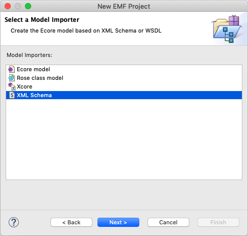
If you don’t have a project already, create one using New -> Other… -> Eclipse Modeling Framework -> EMF Project. Specify a project name and click Next. Several model importers should be proposed.

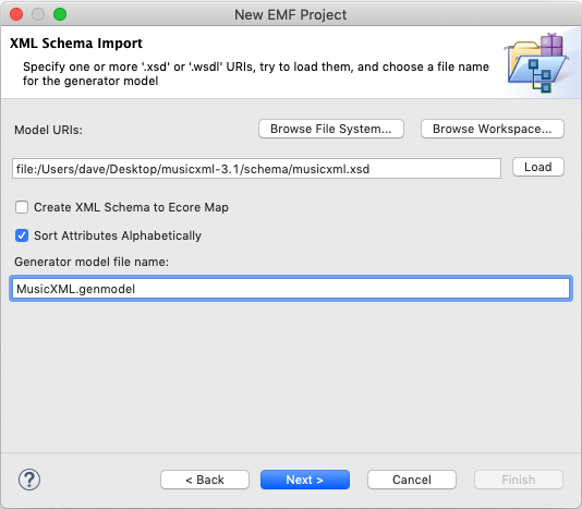
Select XML schema in the list (it should have been installed with the XML Schema Definition SDK) and Click Next. The following page appears:

Click Browse File System… and select the XSD you would like to import. I recommend not to select the option Create XML Schema to Ecore Map. The Generator model file should have an appropriate name already, otherwise you can change it here. I changed the capitalization slightly. Click Next.

On the next page you can specify the file name of the generated ECore model file. It should align with the generator model file name you just specified. Click Finish.

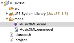
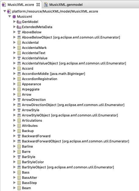
You should end up with a new project containing the folder model. It in turn contains the imported data model in an ecore model file (MusicXML.ecore). It also contains a generator model file named MusicXML.genmodel. If you want to make any adjustments to the data model (classes and attributes/references), this can be done in the ECore model. However, since this an imported model this should not necessary in our case. Below is a screenshot of the imported model:

Adjusting the ECore Model

The only adjustments we need to do for now in the ECore model are:

  1. Right-click the Musicxml package below the root element and choose Show Properties View
  2. Change the Name and the NS Prefix to musicxml (note the lower case m). This is important because this will become part of the java package we will generate.
  3. Set the NS URI to http://www.musicxml.org/xsd/MusicXML

Adjusting the Generator Model

The generator model gives us control about how and where the Java classes for our model will be generated. Select the package below the root element and open the Properties view. Adjust the following settings:

  • Base package: enter the common Java package name prefix which should be put in front of all classes/interfaces/enums to be generated, e.g. org.myapp. Note that the ECore package name will be appended to this prefix automatically. For example, if you use the base package org.myapp and your ECore Package name is musicxml, the code will be generated in the Java package org.myapp.musicxml.
  • Prefix: this is the class name prefix used for EMF-specific classes such as factories and utility classes. I propose to change this to a CamelCase identifier you would put at the beginning of a Java class name. Example: the prefix MusicXML will generate class names such as MusicXMLFactory, MusicXMLPackage, MusicXMLResourceImpl.

Generating the Java Code

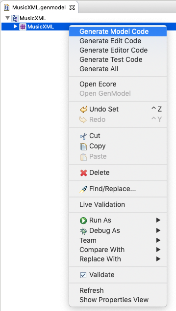
Now it’s time to generate the java classes. In order to do that, right-click on the MusicXML package and choose Generate Model Code.

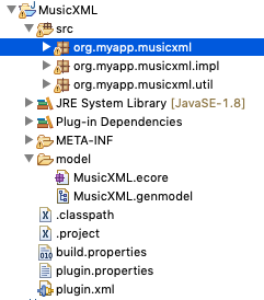
After the operation finishes, you will see lots of interfaces/classes/enums generated in the src folder of your project:

If you want the source code to be generated in another source folder such as src/main/java, this can be adjusted when editing the properties of the root object of the generator model.

Loading an XML File

Now that we have our Java code, we can use the EMF infrastructure to load an XML file to a java model. Loading a file in EMF typically involves:

  1. Creating a ResourceSet
  2. Registering appropriate resource factories in the resource set
  3. Loading a resource by specifying an URI

The following code assumes that a file is loaded from disk, but you could also specify internet URIs instead of the file URI:

1
2
3
4
5
6
7
8
9
10
11
12
13
public static Resource loadMusicXMLFile(File musicXMLFile)
{
    ResourceSetImpl resourceSet = new ResourceSetImpl();
    resourceSet.getResourceFactoryRegistry().getExtensionToFactoryMap().put("xml", new MusicXMLResourceFactoryImpl());
    resourceSet.getResourceFactoryRegistry().getExtensionToFactoryMap().put("musicxml", new MusicXMLResourceFactoryImpl());
 
    // disable DTD resolution since it fails for MusicXML files
    Map<String, Boolean> parserFeatures = new HashMap<>();
    parserFeatures.put("http://apache.org/xml/features/nonvalidating/load-external-dtd", false);
    resourceSet.getLoadOptions().put(XMLResource.OPTION_PARSER_FEATURES, parserFeatures);
 
    return resourceSet.getResource(URI.createFileURI(musicXMLFile.getAbsolutePath()), true);
}

For most scenarios, the first three lines and the last line would be sufficient to load an XML file to a Java model. For MusicXML, I had to tweak the XML parser configuration a bit, because it tried to load MusicXML DTDs from a server which failed. Since we don’t need DTD validation anyway, I disabled the parser feature to load external DTDs. The map with the parser feature settings in turn has to be put as value for the load option key XMLResource.OPTION_PARSER_FEATURES, and EMF will take care of forwarding the parameters to the XML parser. Call getContents() of the returned resource to access the java model representation of the loaded XML file. Here is an example how score parts are accessed in MusicXML files:

1
2
3
4
5
6
EObject eObject = resource.getContents().get(0);
if (eObject instanceof ScorePartwiseType)
{
    ScorePartwiseType scorePartwise = (ScorePartwiseType)eObject;
    processParts(scorePartwise.getPart());
}

If you want to save a MusicXML java model to an XML file, basically use the same code as above, but save your model into the contents of a resource and then call resource.save().

That’s it 🙂 I hope this blog post illustrated how easy and powerful XML to Java object mapping can be when using EMF. Of course this can be done with any correctly structured XSD, not just with MusicXML.

When Logic Destroys Your Audio Files

This post is about a serious bug in Logic, which causes audio files to be damaged. The symptom of this bug is the following error message when opening a previously perfectly working project: One or more audio files changed in length.

Background

This is how I encountered the bug: we had recording sessions with our band and had completed the first session. In the studio, we could listen to all tracks without any problems. After some time, when our sound engineer opened the project again, he encountered the error message above for some files. After listening through the projects, he discovered that a large number of audio clips could not be played back anymore. We had one backup of the project we had made right after the recording session, but unfortunately it contained the same corrupted files. This meant that we had to repeat the recording session 🙁

We had a few more recording sessions, after which we made 3 or 4 backups right away. After we had recorded a whole album, the issue occurred again. The files were corrupted on all backups again, although we could listen to the tracks in the studio without problems. Consequently, the data was corrupted after the recording and before re-opening the Logic project.

Then, our sound engineer noticed the following: when he opened a project for the first time, logic reported 4 corrupted files. When opening the same project again, suddenly 24 files were corrupted. This leads to the conclusion that Logic itself is responsible for destroying the audio files.

Conditions under Which the Bug Occurs

The exact conditions under which the error occurs are not exactly clear, but one of the following things or a combination of those things seems to be involved:

  • Using hard drives or SSDs that are not formatted with an Apple File system (i.e. Mac OS X Journaled or APFS)
  • Using external (hard) drives
  • Using the Comping Feature in Logic (the one where you see multiple takes stacked on each other and can combine them to an “optimal” take)

The files are damaged when logic is closed, which means that even if the project works perfectly before closing the application, there is no guarantee that it will work when opened again.

We experienced these problems with Logic 9, but internet forum posts suggest that it can also happen with Logic Pro X. If someone can confirm, knows the exact error conditions or has any updates, please feel free to comment.

Error Analysis

Logic destroys the audio files in seemingly random order, e.g. in a sequence of 79 audio files recorded for one track the files with numbers 43, 48, 56, 57, 58, 59, 65, 74 and 79 were corrupted.

For a more thorough analysis, I compared working files with corrupted files using a Hex editor, in which each single byte in the file can be visualized in hexadecimal representation. The first bytes of an intact wave file look like this:

For a detailed description of each byte, refer to this page. In short, these are the contents of the wave file header:

  • Bytes 1-4: RIFF chunk descriptor
  • Bytes 5-8: chuck size (total number of bytes in the file after this block)
  • Bytes 9-12: format (in this case WAVE)
  • Bytes 13-16: fmt-subchunk header (contains fmt )
  • Bytes 17-20: subchunk 1 size (in this case 16 for PCM)
  • Bytes 21-22: audio format (1 = PCM)
  • Bytes 23-24: number of channels (1 = Mono, 2 = Stereo, etc.)
  • Bytes 25-28: sample rate (e.g. 44,100 Hz)
  • Bytes 29-32: byte rate: number of bytes required to store 1 second of audio for all channels (= sample rate * number of channels * bits per sample / 8)
  • Bytes 33-34: block align: number of bytes required to store one sample in all channels (= number of channels * bits per sample / 8)
  • Bytes 34-36: resolution in bits per sample, e.g. 8, 16 or 24 bits
  • Bytes 37-40: data chunk header (contains data)
  • Bytes 41-44: number of bytes representing the raw audio data
  • Bytes 45ff.: raw audio data

Now let’s have a look at a destroyed audio file:

If the bug occurs, Logic fails to write the wave header correctly. Instead, the file contains only zeroes in the first 44 bytes, which is exactly the length of the wave header. The good news: the raw audio data, starting at byte 45, is still intact (note that the hex editor starts counting bytes at index 0).

If such a corrupted wave file is opened, logic can’t read the header and assumes a default 8 bit setting, which leads to a misinterpretation of the audio data. Consequently, the length of the file will also be misinterpreted. Furthermore, the interpretation will be even more off because a wrong sample rate is assumed. Not good.

Repairing the Audio Files

As a preliminary fix, you can restore the destroyed files by copying a wave file header (i.e. the first 44 bytes) from a correct file (with matching sample rate and bit depth) to a corrupted file in a hex editor.

Update August 29, 2019: It was confirmed that this also works for AIFF files. In this case, the first 512 bytes have to be copied. Thank you very much to Sawyer Wildgen for sharing this!

A wave file header specifying a sample rate of 44.100 Hz and 24 bit resolution starts with bytes similar to these (in hexadecimal representation):

1
52 49 46 46 5B 89 3E 00 57 41 56 45 66 6D 74 20 10 00 00 00 01 00 01 00 44 AC 00 00 CC 04 02 00 03 00 18 00 64 61 74 61 6B 5C 3E 00

However, one potential issue now could still be that the (sub)chunk sizes (bytes 5-8 and 41-44) are not correct, but most audio editors don’t check these values. If you want to correct these as well, make sure that you use the correct little endian representation for these byte groups. This means the byte order is reversed. A complete example is given below.

The formulas to calculate the correct values for WAVE files are:

  • chunk size = <file size in bytes> - 8
  • data chunk size = <file size in bytes> - 44

Integer to Little Endian Hex Conversion

Example: Converting the number 44,100 to a little endian hex number:

  1. Convert number to hex using a scientific calculator or an online converter such as this one. The result is: AC 44. Note that this result comprises two bytes and is encoded big endian (most significant byte first).
  2. Make sure the result is padded to the correct byte size. If the field in the header is 4 bytes, we have to add two zero bytes at the beginning: 00 00 AC 44
  3. Reverse the byte order: 44 AC 00 00. The result is now little endian (least significant byte first), as required by the wave header specification.

To confirm, you can open a working wave file with 44,100 Hz sample rate in a hex editor and check bytes 25-28, which will contain 44 AC 00 00.

Using Wave Recovery Tool to Restore the Wave File Headers

Because quite many files were damaged in our case, I did not want to fix all wave headers manually. Therefore, I developed a program which can fix the wave files all at once. Wave Recovery Tool is available on github and is published under the terms of the GNU General Public Licence.

Conclusion

This post reveals a serious bug in Logic, which can potentially destroy hours and weeks of hard work. Fortunately, the data can be restored completely either manually or using a Wave Recovery Tool I developed. I seriously hope that this bug will be fixed soon or is already fixed in recent versions of Logic.

Notes Regarding AIFF Files

In this blog post, I demonstrated the issue by means of wave file header structures. The same can be done for AIFF files, however the header structure is more complex. The good news: I extended Wave Recovery Tool and now it is also possible to restore AIFF files under certain conditions.