I’m currently building a home automation system based on the incredibly powerful openHAB 2 platform. We already have a few remotely switchable 433 MHz power outlets by the manufacturer Brennenstuhl in our home which we currently switch using the provided remote controls. I was wondering whether we could control them from the OpenHAB platform as well, and indeed found a way to achieve this.
My openHAB 2 instance does not run on a Rasberry Pi, but on a dedicated Ubuntu Server. If your platform is Raspberry, your hardware setup and configuration might be different, but still I think this article will be useful for the OpenHAB binding configuration.
Hardware
First, I looked for a suitable device capable of sending and receiving 433 MHz signals. I ended up with a nanoCUL device connected via USB. There are many DIY nanoCUL kits available on the internet that you can assemble yourself, but there are also pre-built nanoCULs available. I chose the latter and ordered an assembeled nanoCUL USB device including an antenna and a USB adapter. It looks like this:
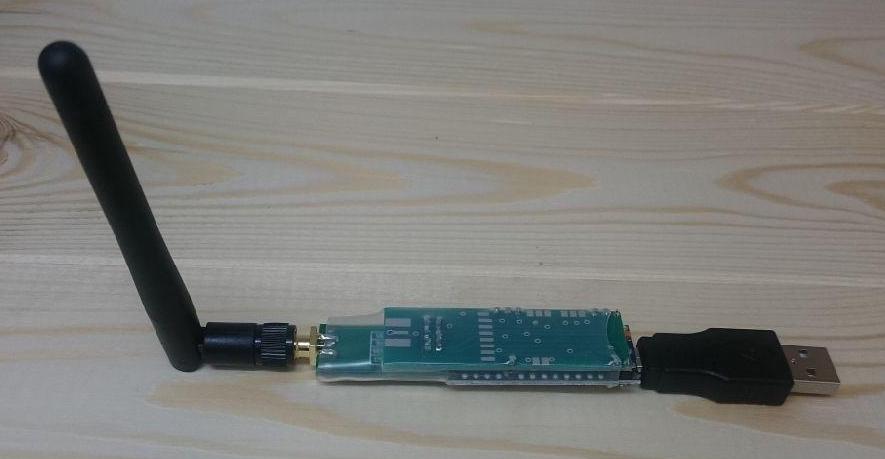
nanoCUL with antenna and USB adapter
OpenHAB Binding
After some research I found a suitable binding to integrate nanoCUL with openHAB: it is called Intertechno Binding. It is an older v1 binding, and is not displayed in my Bindings list after the installation (even when activating the Include Legacy 1.x Bindings option). But it works nonetheless.
To configure the nanoCUL, edit the file services/culintertechno.cfg and add the following configuration:
1
2
3
| device=serial:/dev/ttyUSB1
baudrate=38400
parity=NONE |
device=serial:/dev/ttyUSB1
baudrate=38400
parity=NONE
You have to adjust the device (in my case /dev/ttyUSB1) to the device matching the nanoCUL on your system. To find out which device it is, I used a script I found in this stackexchange answer.
Binding the Device using a Unique Identifier
After a few reboots I discovered an issue: sometimes, the nanoCUL was bound to /dev/ttyUSB1, other times to /dev/ttyUSB0. This lead to errors and conflicts in openHAB. To solve this problem, I used a device path like the following in services/culintertechno.cfg:
1
| device=serial:/dev/serial/by-id/<id of your nanoCUL> |
device=serial:/dev/serial/by-id/<id of your nanoCUL>
You can find the device ID of your nanoCUL using
1
| ls -la /dev/serial/by-id/ |
ls -la /dev/serial/by-id/
But when I started openHAB2, the following error occurred:
1
| org.openhab.io.transport.cul.CULDeviceException: gnu.io.NoSuchPortException |
org.openhab.io.transport.cul.CULDeviceException: gnu.io.NoSuchPortException
I found out that this can be solved by adding the device path to the java startup options of openhab2. In my case, these can be configured in /etc/default/openhab2:
1
| EXTRA_JAVA_OPTS="-Dgnu.io.rxtx.SerialPorts=/dev/serial/by-id/<id of your nanoCUL>" |
EXTRA_JAVA_OPTS="-Dgnu.io.rxtx.SerialPorts=/dev/serial/by-id/<id of your nanoCUL>"
After adding the option and restarting openhab2 with sudo service openhab2 restart, the error disappeared and now the system has the correct device association after every reboot.
Item Configuration
The tricky part was to find out which codes to send to switch the power outlets on or off. After long research, I found this FHEM Wiki page which finally helped me to figure out the codes. The power outlets are configured with DIP switches like the following:
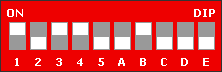
The first 5 switches identify the logical group of power outlets. The remote control that comes with the power outlets has the DIP switches 1-5 only (excluding A-E). A-E identifies one of 5 power outlets in the group.
To derive the code to be sent from openHAB, you just have to translate the switch states into a sequence of 0 and F, where 0 corresponds to “switch up” and F corresponds to “switch down” (I did not get why “switch up” is encoded with a lower value than “switch up”, but anyway this is how it works for me). So for the switch states shown above, the code is
0F00FF0FFF
This is the basic code to address a specific power outlet in a specific group, where the first five digits encode the group and the last five hex digits the outlet in the group. To control whether the outlet should be turned on or off, one the following two codes has to be appended: FF = ON or F0 = OFF. So in conclusion, to switch on the above outlet, the complete code is
0F00FF0FFFFF
and to switch it off, the code is
0F00FF0FFFF0
In the item configuration, this is added as follows:
1
| Switch MyOutlet_B "My Outlet B" {culintertechno="type=raw;commandOn=0F00FF0FFFFF;commandOff=0F00FF0FFFF0"} |
Switch MyOutlet_B "My Outlet B" {culintertechno="type=raw;commandOn=0F00FF0FFFFF;commandOff=0F00FF0FFFF0"}
And that’s it folks, it works like a charm for me 🙂 I hope this post will be useful to others who want to integrate their 433 MHz power outlets in openHAB.
Update for OpenHAB 3
The Intertechno Binding is not supported anymore on openHAB 3, but I found a way to control 433 MHz devices using the Serial Binding. After some research I found out that the intertechno binding basically just sends the command string (described in detail in the previous section) prefixed with the string is and followed by a newline character to a serial interface. So for the example above, the resulting string looks like this:
is0F00FF0FFFFF\n
To send commands via the serial binding, first create a serial bridge with the following settings:
- Serial Port: the USB port where the nanoCUL is connected, e.g.
/dev/ttyUSB0 or /dev/serial/by-id/<id of your nanoCUL>
- Baud Rate: 38400
- Data Bits: 8
- Parity: None
- Stop Bits: 1
Create a new serial device for each outlet to be connected. Choose the serial bridge created in the previous step as parent bridge. For the pattern match setting (which is required) I entered a regular expression matching everything: .*
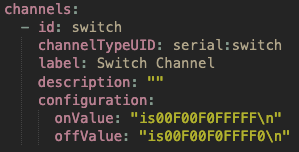
The next step is to add a switch channel with the following settings: The tricky part is to add a newline character to the command. If it is added to the command string in the UI directly,
 \n is interpreted as the literal sequence of a backslash and the character n, not as newline. The trick is to switch to the Code tab, add double quotes around the commands and then insert \n:
 After saving the configuration, the commands are sent correctly. If you want to change the command later, the UI presentation is a bit strange: there are pipe sysmbols, the quotes and the newlines are gone and the commands are in the next lines, respectively:
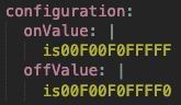 If you want to modify the command again, you have to restore the state as shown in the first screenshot. Not sure if this the intended UI behavior. But anyways it it possible to add newlines as illustrated in the first screenshot.
A post that helped me a lot in which I also shared my solution can be found here.
 We will need this data later to connect the MQTT broker.
 Add an MQTT Broker
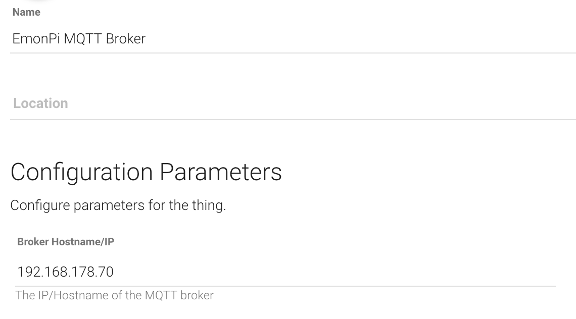 Also, the username and password you configured in the MQTT configuration of your EmonHub (see above) must be entered:
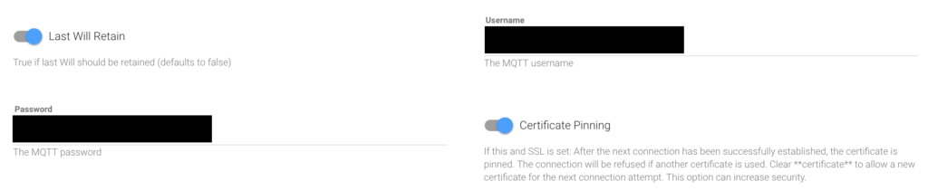 Add a MQTT Thing
 Add openHAB Items